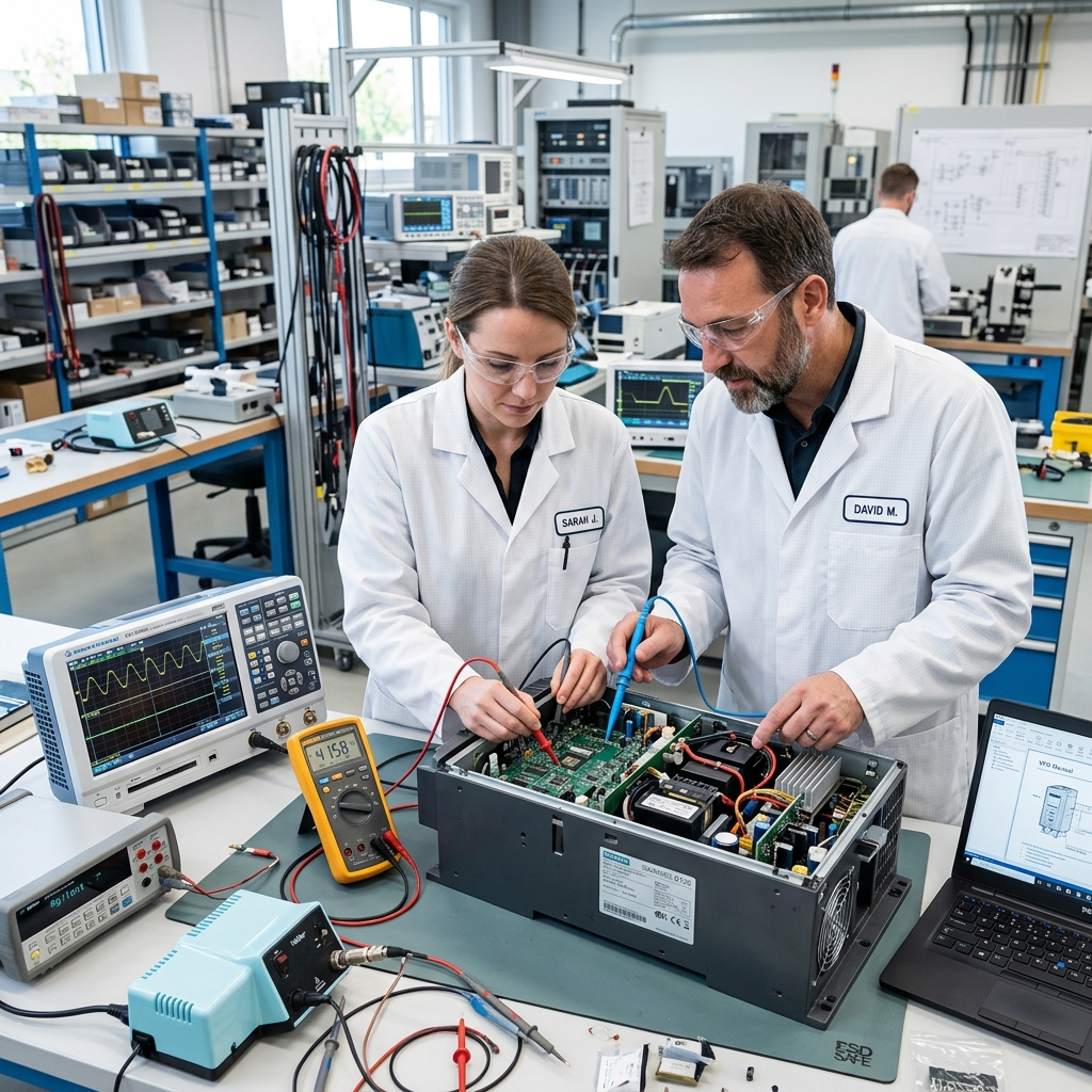
Supported Allen-Bradley Hardware Platforms
Apex Industrial Control restores active, legacy, and obsolete Rockwell Automation hardware with 24-48 hour emergency rush turnaround options.
PowerFlex AC Drives
PowerFlex 525, 523, 40, 70, 700, 753, and 755 drives. Gate driver optocoupler rework, IGBT bridge replacement, and 460V dyno testing.
ControlLogix & CompactLogix
1756-L7x/L8x CPUs, 1756-PA75/PB75 power supplies, 1769 CompactLogix, and discrete/analog I/O module micro-soldering rework.
Kinetix Servo Drives
Kinetix 300, 6000, 6500, and 5700 multi-axis servo positioners. Encoder feedback resolution, phase alignment, and power stage rebuilds.
PanelView Plus HMIs
PanelView Plus 6, 7, and legacy PanelView 1000/1400. Touchscreen digitizer replacement, CCFL backlight LED retrofits, and logic card repair.
Allen-Bradley PowerFlex Fault Code Directory & Bench Repair Protocols
Comprehensive diagnostic protocols, root-cause hardware failure analysis, and Virginia bench repair workflows for facility engineers and maintenance teams.
F2: Auxiliary Input
External safety interlock or auxiliary terminal contact opened unexpectedly during operation.
Loose auxiliary interlock wiring, tripped external overload relay, or open emergency stop contact on digital input terminal 2.
Inspect physical wiring on digital input terminals. Verify external safety relays, door switches, and thermal overloads are closed. Measure DC voltage across digital input terminals.
At Apex Industrial Control, bench engineers inspect the optocoupler isolator array and digital input buffer ICs. Corrupted optical isolation channels are replaced with OEM components before 460V load validation.
F3: Power Loss
DC bus voltage dropped below minimum operating limit while drive was running.
Transient incoming 3-phase line drop, open main line fuse, failing pre-charge contactor/relay, or high resistance line connection.
Check incoming 3-phase AC voltage (L1, L2, L3) with a DMM under load. Inspect main line fuses and contactors for voltage drops or phase imbalance.
Apex Industrial Control technicians evaluate the internal DC bus pre-charge relay, current-limiting thermistors, and pre-charge control circuitry. Degraded pre-charge components are replaced prior to 460V dyno testing.
F4: UnderVoltage
DC bus voltage fell below the minimum cutoff threshold (approx 300VDC on 480V units).
Aging DC bus electrolytic capacitors losing capacitance, degraded 3-phase rectifier diode bridge, or utility brownout.
Measure main DC bus voltage across terminals (+DC and -DC). If incoming AC line voltage is nominal but DC bus voltage sags significantly, internal capacitor bank failure is indicated.
Apex Industrial Control tests DC bus capacitor banks for Equivalent Series Resistance (ESR) and total microfarad capacity. Depleted electrolytic banks and bridge rectifiers are replaced with high-temp industrial components.
F5: OverVoltage
DC bus voltage exceeded maximum safe limit (approx 810VDC on 480V units).
Excessive regenerative energy returned from motor during rapid deceleration, missing or failed dynamic braking resistor, or improper ramp-down parameters.
Increase deceleration time (Parameter A437) or enable S-curve acceleration. Measure resistance of external dynamic braking resistor connected to BR+ and BR- terminals.
Apex Industrial Control inspects internal brake chopper MOSFET transistors and voltage sensing feedback dividers. Damaged braking transistors are replaced and stress-tested on our 460V dynamometer rig.
F6: Motor Stall
Drive delivered maximum current to motor without detecting expected speed increase or shaft rotation.
Mechanical machine jam, seized gearbox/bearing, incorrect motor nameplate parameters, or loose motor cable connections.
Uncouple motor from mechanical load and spin motor shaft by hand. Verify motor nameplate Amps, Volts, and Frequency parameters match drive programming. Run drive uncoupled.
Apex Industrial Control checks current feedback LEM sensors and gate driver timing logic to rule out false current feedback signals before full-load motor testing.
F7: Motor Overload
Internal thermal I2t model calculated motor operating above rated thermal capacity.
Continuous mechanical overload, low-speed operation without auxiliary cooling fan, or incorrect motor thermal overload current parameter setting.
Check mechanical load for binding. Measure actual operating AC current on motor output leads (U, V, W) with a clamp meter and compare to Parameter P033 (Motor OL Current).
At Apex Industrial Control, current measurement circuits are calibrated on precision test benches to guarantee accurate motor thermal modeling.
F8: Heatsink OvrTmp
Drive power module heatsink temperature exceeded maximum safety threshold (approx 90°C-100°C).
Clogged heatsink cooling fins, failed internal brushless cooling fan, ambient enclosure temperature above 50°C, or dried-out thermal paste under IGBT.
Inspect internal cooling fan for rotation. Clean dust and debris from heatsink air channels using compressed air. Measure ambient cabinet temperature.
Apex Industrial Control replaces internal cooling fans with high-CFM dual-ball-bearing units, cleans heatsink mating surfaces, and applies military-grade thermal compound beneath power modules.
F12: HW OverCurrent
Instantaneous hardware overcurrent trip triggered by internal power module hardware.
Short circuit across output terminals U, V, W, shorted motor winding, or catastrophic IGBT module transistor breakdown/punch-through.
Disconnect motor cables from U, V, W terminals immediately. Perform diode check with DMM across DC bus and output phase terminals. If diode check fails (shows 0 ohms), drive is shorted internally.
Apex Industrial Control performs complete power module rebuilding: removing shorted IGBT modules, replacing blown gate driver optocouplers and surface-mount gate resistors, and validating under 460V dyno load.
F13: Ground Fault
Current imbalance detected between output phases and chassis ground (current leaking to ground).
Moisture or insulation breakdown in motor windings, damaged motor lead cable, or faulty ground current transformer inside drive.
Disconnect motor lead wires from drive output terminals. Megger test motor cable and motor windings at 1000VDC to ground. Resistance should exceed 10 MΩ.
If motor and cables test good, Apex Industrial Control inspects internal zero-sequence current transformers and hall-effect sensing circuits for component drift.
F29: Analog In Loss
Analog input signal dropped below configured minimum threshold (e.g. 4mA on a 4-20mA loop).
Broken analog signal wire, loose terminal screw, failed PLC analog output card, or blown analog input ADC converter on drive control board.
Measure DC voltage (0-10V) or current (4-20mA) directly across analog input terminals (Anlg In 1/2) with a calibrated multimeter.
Apex Industrial Control repairs damaged Analog-to-Digital Converter (ADC) channels, operational amplifiers, and surface-mount input protection diodes on the control board.
F33: Auto Rstrt Tries
Drive attempted maximum programmed automatic fault reset attempts without clearing underlying fault.
Persistent recurring fault condition (such as intermittent low line voltage or repeating overload) exceeding Parameter A541 attempts.
Inspect drive fault buffer log to identify the root fault causing repeated trips. Clear underlying fault cause before resetting.
Apex Industrial Control evaluates non-volatile event logging memory and control processor stability on specialized test benches.
F38: Phase U to Gnd
Phase U output terminal detected direct short circuit to chassis ground.
Phase U IGBT transistor punch-through, damaged motor cable insulation on Phase U, or burned motor stator winding.
Disconnect output wire from Terminal U. Resistance test Terminal U to drive ground chassis using DMM. 0 Ohms indicates shorted internal IGBT output transistor.
Apex Industrial Control desolders power module, replaces Phase U IGBT silicon, rebuilds driver optocoupler channels, and ultrasonically cleans circuit traces.
F39: Phase V to Gnd
Phase V output terminal detected direct short circuit to chassis ground.
Phase V IGBT transistor breakdown or Phase V motor lead ground fault.
Disconnect output wire from Terminal V. Perform multimeter diode and resistance test between Terminal V and chassis ground.
Apex Industrial Control replaces shorted power IGBT components, repairs gate resistors, and validates output waveform balance on digital oscilloscopes.
F40: Phase W to Gnd
Phase W output terminal detected direct short circuit to chassis ground.
Phase W IGBT transistor failure or Phase W motor winding ground short.
Disconnect Phase W motor cable. Resistance test Terminal W to ground. 0 Ohms confirms internal drive transistor failure.
Apex Industrial Control remanufactures inverter power board, replaces gate optocouplers, and full-load tests unit on 460V dynamometer.
F41: Phase UV Short
Direct phase-to-phase output short circuit detected between Phase U and Phase V terminals.
Short circuit across output terminals U and V, crushed motor lead cable, or simultaneous upper/lower IGBT gate breakdown.
Disconnect motor wires U and V. Measure resistance between Terminals U and V. Infinite resistance should be present.
Apex Industrial Control replaces shorted IGBT power module, repairs gate drive timing logic, and tests under full load.
F42: Phase UW Short
Direct phase-to-phase output short circuit detected between Phase U and Phase W terminals.
Phase-to-phase insulation short between U and W leads or IGBT upper/lower bridge cross-conduction.
Disconnect U and W motor leads and measure resistance between output terminals U and W.
Apex Industrial Control desolders shorted IGBTs, rebuilds gate driver optocouplers, and conducts 460V load validation.
F43: Phase VW Short
Direct phase-to-phase output short circuit detected between Phase V and Phase W terminals.
Direct phase-to-phase short between Terminals V and W or internal IGBT silicon breakdown.
Disconnect motor leads V and W. Perform meter resistance check between Terminals V and W.
Apex Industrial Control overhauls inverter power stage, replaces damaged current sensors, and load tests unit on dynamometer.
F48: Params Defaulted
Drive parameters reset to factory default values due to non-volatile memory corruption.
Power glitch during parameter save sequence, depleted internal memory backup supercapacitor, or EEPROM chip failure.
Re-enter motor nameplate data and application parameters manually or download saved parameter backup via Connected Components Workbench (CCW).
Apex Industrial Control replaces faulty non-volatile EEPROM ICs and memory backup batteries on control boards.
F63: SW OverCurrent
Software-based programmable current limit exceeded during rapid acceleration or heavy transient load.
Acceleration time too short (Parameter P039), improper torque boost setting, or sudden mechanical load spike.
Increase acceleration time. Inspect mechanical application for sudden load engagement during motor start.
Apex Industrial Control tests current sense feedback resistors and operational amplifiers for drift.
F64: Drive Overload
Drive operating current exceeded continuous thermal rating beyond safe I2t boundaries.
Undersized variable frequency drive for the connected motor or duty cycle exceeding drive rating.
Verify drive continuous current rating matches actual peak load current. Measure operating temperature.
Apex Industrial Control performs full thermal imaging and load bank testing to verify internal heat dissipation.
F70: Power Unit
Critical internal power board hardware failure; gate driver logic or current sensing circuitry malfunction.
Blown gate driver optocouplers, shorted DC-DC auxiliary power supply rail, or corrupted power board ASIC signature.
Cycle main AC input power. If F70 fault immediately recurs upon power-up with motor disconnected, internal hardware is damaged.
Apex Industrial Control desolders power board components, replaces gate driver optocouplers, rebuilds 15V/5V DC-DC power supply circuits, and 460V load tests.
F71: Network Loss
Ethernet/IP communication connection dropped between PLC and drive option card.
Damaged RJ45 Ethernet cable, IP address conflict, PLC processor stop mode, or loose option card ribbon connector.
Inspect Ethernet cable and status LEDs on embedded Ethernet port. Verify IP address, subnet mask, and gateway parameters.
Apex Industrial Control repairs damaged Ethernet PHY chips, pulse transformers, and option card bus connectors.
F81: Comm Loss
Serial DSI / RS-485 communication link disconnected.
Loose DSI cable connection, broken serial RS-485 wire, or baud rate mismatch.
Check DSI cable pinout and seating. Verify communication baud rate parameters (Parameter C123).
Apex Industrial Control replaces damaged RS-485 transceiver ICs (MAX485/SN75176) on control board.
f87: AutoTune Fail
Drive failed automatic motor stator resistance/inductance calculation procedure.
Motor leads disconnected during test, motor shaft rotated during static tune, or motor size incompatible with drive rating.
Ensure motor leads are securely connected and motor shaft is completely stationary during AutoTune (Parameter P040).
Apex Industrial Control checks output current sensor linear response on precision test benches.
F91: Encoder 1 Loss
Encoder pulse feedback signal missing or corrupted while drive running in closed-loop mode.
Broken encoder cable wire, missing 5V/12V encoder power supply, or failed optical encoder disk on motor.
Measure DC supply voltage to encoder card. Inspect A, B channel quadrature signals with an oscilloscope while rotating motor.
Apex Industrial Control repairs differential line receiver ICs (26LS32) on encoder feedback option modules.
F100: Parameter Checksum
Internal non-volatile memory CRC checksum mismatch detected upon power-up initialization.
Corrupted micro-controller flash memory, failed EEPROM IC, or severe electrical noise burst during write.
Perform factory parameter reset (Parameter P041 to 1). If drive fails to reset or F100 persists, control board memory hardware is corrupted.
Apex Industrial Control desolders damaged EEPROM/Flash chips, programs fresh firmware hex code, and recalibrates control board.
F111: Safety Open
Dual-channel Safe Torque-Off (STO) safety circuit input contact opened.
Tripped safety gate switch, emergency stop button pressed, or loose wiring on STO safety terminals (S1, S2, Safety+).
Check 24VDC safety voltage across terminals S1, S2, and Safety+. Verify safety relay is energized.
Apex Industrial Control replaces failed optocouplers and safety channel monitor transistors on STO board.
F112: Pwr Brd Fail
Power module hardware signature mismatch or internal auxiliary DC supply rail failure.
Blown internal SMPS auxiliary power supply transformer, failed DC bus voltage divider, or unseated power board ribbon connector.
Cycle AC input power. If F112 recurs instantly, power board hardware requires bench overhaul.
Apex Industrial Control rebuilds auxiliary switch-mode power supply, replaces power board interface ICs, and 460V load tests.
F122: I/O Board Fail
Main control module I/O expansion board microprocessor communication lockup.
Unseated ribbon cable between control cassette and power module, micro-controller lockup, or shorted I/O terminal.
Remove power cassette and re-seat main interconnect ribbon cable. Check for shorted external 24V I/O wiring.
Apex Industrial Control repairs damaged bus interface logic chips, replaces corrupted control microprocessors, and stress tests.
Event 2: Aux Input
Digital input configured as auxiliary interlock opened during drive operation.
External safety relay contact open, door switch tripped, or loose digital input wiring on Option Slot I/O module.
Inspect external interlock circuit. Measure DC voltage on digital input terminal mapped to Auxiliary Input function.
Apex Industrial Control bench tests Option Slot I/O module buffer ICs and optical isolator channels.
Event 3: Power Loss
Main AC line input voltage dropped below acceptable operating limit while drive was active.
3-phase AC utility drop, blown line fuse, input SCR pre-charge circuit fault, or loose line reactor connections.
Check incoming 3-phase AC voltage (L1, L2, L3). Inspect line fuses and main input circuit breaker under load.
Apex Industrial Control inspects input SCR firing circuit, gate pulse transformers, and DC pre-charge logic.
Event 4: UnderVoltage
DC bus voltage dropped below minimum operating cutoff threshold.
Aged DC bus capacitor bank losing capacitance, line brownout, or degraded pre-charge circuit.
Measure DC bus voltage at test points. Compare measured DC voltage to incoming AC RMS line voltage (DC = AC × 1.35).
Apex Industrial Control evaluates DC capacitor ESR, replaces weak capacitor banks, and rebuilds voltage divider circuits.
Event 5: OverVoltage
DC bus voltage exceeded upper safety threshold (approx 810VDC on 480V units).
High regenerative energy during rapid motor deceleration, open dynamic brake resistor, or faulty brake chopper transistor.
Increase Decel Time parameter. Measure resistance of dynamic brake resistor connected to BR terminals.
Apex Industrial Control tests internal brake chopper IGBT modules, replaces driver optocouplers, and validates on 460V dyno.
Event 7: Motor Overload
Drive internal thermal I2t algorithm calculated motor heating above safe limits.
Continuous mechanical load exceeding motor rating, low-speed operation without external fan, or improper motor parameters.
Measure motor phase current with clamp meter. Verify motor nameplate data in Parameter 26 (Motor NP Amps).
Apex Industrial Control calibrates output current transducers (LEM modules) on precision test stands.
Event 8: Heatsink OvrTemp
Main inverter heatsink temperature sensor exceeded maximum allowed thermal threshold.
Clogged heatsink air tunnel, failed main cooling blower, ambient cabinet temperature over 50°C, or dried thermal paste.
Inspect main cooling fan for rotation. Clean heatsink fins with compressed air. Verify cabinet AC cooling unit is operational.
Apex Industrial Control replaces main cooling blowers, cleans heatsink assemblies, and reapplies thermal grease under power modules.
Event 9: Trnsistr OvrTemp
Calculated internal IGBT junction temperature exceeded silicon thermal safety rating.
Severe short-term current overload, failing IGBT module internal bond wires, or degraded heatsink thermal interface.
Check operating load current. If fault occurs immediately at low load, internal IGBT thermistor feedback is shorted.
Apex Industrial Control replaces damaged IGBT power modules, thermistor feedback circuits, and 460V load tests.
Event 10: DynBrake OvrTemp
Dynamic brake chopper transistor or external brake resistor thermal model limit exceeded.
Excessive braking duty cycle, undersized dynamic braking resistor, or shorted brake chopper transistor.
Verify dynamic resistor pulse rating and duty cycle. Measure resistor resistance while disconnected from drive.
Apex Industrial Control bench tests dynamic brake chopper transistors, gate firing logic, and thermal protection ICs.
Event 12: HW OverCurrent
Instantaneous hardware overcurrent trip detected via internal LEM current sensors.
Direct phase-to-phase output short circuit, shorted motor winding, or catastrophic IGBT power module breakdown.
Disconnect output cables U, V, W. Measure diode drop across DC bus and output terminals using DMM. 0V indicates shorted IGBT.
Apex Industrial Control desolders damaged power module, replaces gate driver board optocouplers and SMD resistors, and 460V dyno tests.
Event 13: Ground Fault
Sum of output phase currents (U+V+W) does not equal zero, indicating current leaking to ground.
Moisture in motor conduit, motor stator ground short, or damaged output lead cable insulation.
Disconnect motor leads from U, V, W terminals. Megger test output cables and motor windings to ground at 1000VDC.
If motor passes megger test, Apex Industrial Control inspects internal zero-sequence CTs and current feedback amplifiers.
Event 14: Ground Warning
Early detection of low-level ground leakage current on output phases before full fault trip.
Long motor cable capacitance leakage, developing motor insulation breakdown, or damp motor enclosure.
Inspect motor junction box for moisture or dirt accumulation. Measure insulation resistance.
Apex Industrial Control checks ground leakage detection sensitivity circuits on main power interface board.
Event 15: Load Loss
Motor load current dropped below minimum expected threshold while drive running.
Broken drive belt, sheared gearbox coupling pin, or dry pump running empty.
Inspect mechanical drive train, belts, and mechanical couplings. Check Parameter 441 (Load Loss Current level).
Apex Industrial Control verifies output current feedback linearity across full speed range.
Event 33: Auto Rstrt Tries
Drive attempted maximum programmed automatic fault reset attempts without resolving issue.
Persistent repeating fault (e.g. line sag or overvoltage) exceeding parameter retry count.
Check drive event log to determine primary fault code triggering repeated trips.
Apex Industrial Control evaluates non-volatile event logging RAM and control pod processor logic.
Event 38: Phase U to Gnd
Phase U output phase detected direct short to chassis ground.
Phase U IGBT transistor breakdown or Phase U motor cable short to ground.
Disconnect output wire U. Perform resistance test between Terminal U and drive chassis ground.
Apex Industrial Control replaces shorted Phase U IGBT, repairs gate driver optocouplers, and load tests.
Event 39: Phase V to Gnd
Phase V output phase detected direct short to chassis ground.
Phase V IGBT transistor breakdown or Phase V motor lead ground short.
Disconnect output wire V and measure resistance between Terminal V and chassis ground.
Apex Industrial Control desolders damaged power module, replaces gate drive channels, and load tests.
Event 40: Phase W to Gnd
Phase W output phase detected direct short to chassis ground.
Phase W IGBT transistor breakdown or Phase W motor lead ground short.
Disconnect output wire W. Measure resistance between Terminal W and chassis ground.
Apex Industrial Control rebuilds power stage board, replaces damaged current transducers, and 460V load tests.
Event 41: Phase UV Short
Direct output short circuit detected between Phase U and Phase V output terminals.
Phase-to-phase short in motor cable, shorted motor stator windings, or IGBT bridge cross-conduction.
Disconnect motor wires U and V. Check resistance across Terminals U and V with DMM.
Apex Industrial Control replaces shorted IGBT silicon modules, gate firing optocouplers, and load tests.
Event 42: Phase UW Short
Direct output short circuit detected between Phase U and Phase W output terminals.
Output cable phase-to-phase short between U and W or internal IGBT transistor punch-through.
Disconnect motor wires U and W and test resistance across Terminals U and W.
Apex Industrial Control remanufactures inverter power board, replaces gate optocouplers, and 460V load tests.
Event 43: Phase VW Short
Direct output short circuit detected between Phase V and Phase W output terminals.
Direct phase-to-phase short between Terminals V and W or internal IGBT silicon breakdown.
Disconnect motor leads V and W. Perform meter resistance check between Terminals V and W.
Apex Industrial Control desolders damaged IGBTs, repairs gate driver board, and 460V dyno load tests.
Event 48: Params Defaulted
Drive parameters reset to factory default values due to non-volatile memory corruption.
Power glitch during parameter write, depleted memory battery on main control pod, or corrupted flash memory.
Restore parameters from HIM memory copy or Connected Components Workbench (CCW) software backup.
Apex Industrial Control replaces non-volatile Flash/EEPROM chips and memory backup batteries on control pod.
Event 63: SW OverCurrent
Software current limit trip during rapid acceleration or sudden shock load.
Accel time too fast, improper vector control motor parameters, or mechanical jam during cycle.
Increase Accel Time parameter. Perform motor AutoTune procedure.
Apex Industrial Control checks current sense amplifier linearity and feedback resistors for drift.
Event 64: Drive Overload
Continuous operating current exceeded drive thermal continuous rating.
Undersized variable frequency drive for application or operating above rated duty cycle.
Check motor load current. Verify drive continuous rating matches peak process demand.
Apex Industrial Control inspects internal thermistor circuits and heatsink thermal transfer.
Event 70: Power Unit
Fiber-optic communication or ASIC interface failure between main control pod and power module board.
Damaged fiber-optic cable, blown gate driver board ASIC chip, or failed internal 15V auxiliary power supply rail.
Re-seat fiber-optic cables connecting control pod to power unit. If Event 70 persists, internal hardware is damaged.
Apex Industrial Control desolders power board components, replaces fiber-optic transmitters/receivers, gate driver ICs, and 460V dyno tests.
Event 71: Port 1 DPI Loss
Drive Peripheral Interface (DPI) communication lost on Option Slot 1.
Loose option card seating, damaged option card ribbon connector, or defective option module in Slot 1.
Power down drive, remove option module from Slot 1, clean edge contacts, and re-seat firmly.
Apex Industrial Control repairs damaged DPI bus interface transceivers and backplane connectors on main control pod.
Event 81: Port 2 DPI Loss
DPI communication lost on Option Slot 2.
Loose option module connection in Slot 2 or communication option card lockup.
Re-seat option card in Slot 2. Inspect option module status LEDs.
Apex Industrial Control repairs option card interface logic and microprocessors on control pod.
Event 82: Port 3 DPI Loss
DPI communication lost on Option Slot 3.
Option module fault or loose backplane bus connection in Slot 3.
Inspect option card seating and wiring in Slot 3.
Apex Industrial Control bench tests Option Slot 3 interface bus and replaces failed transceiver ICs.
Event 91: Encoder 1 Loss
Universal feedback encoder card pulse loss detected during closed-loop operation.
Broken encoder cable, missing 5V/12V encoder power, or defective optical encoder on motor shaft.
Inspect encoder cable shield and differential signal wires. Measure DC power output on encoder card terminals.
Apex Industrial Control bench tests universal feedback card channels on high-speed pulse generator rigs.
Event 100: Parameter Chksum
Non-volatile memory CRC checksum validation failed upon power-up initialization.
Corrupted control pod micro-controller flash memory or failed non-volatile EEPROM IC.
Attempt factory reset via HIM module. If Event 100 cannot be cleared, control pod memory hardware is corrupted.
Apex Industrial Control desolders damaged flash memory chips, re-flashes factory microcode, and recalibrates control pod.
Event 122: I/O Bd Fail
Control pod I/O module microprocessor hardware failure.
Hardware failure on I/O option card, blown analog input ADC, or unseated control pod ribbon cable.
Remove power, re-seat I/O option cards, and check for shorted external 24V field wiring.
Apex Industrial Control replaces damaged microprocessors, analog input operational amplifiers, and bus interface ICs.
How Our Ship-In Repair Process Works
From initial component curve tracing to 460V full-load dyno testing, our ISO-aligned B2B bench protocol ensures fast, reliable restoration.
Submit Fault Details & Get Shipping Slip
Fill our quick online form or call directly with your VFD/PLC model and error code. Receive your free pre-addressed shipping label and repair form.
Component-Level Diagnosis & Approval
We test components under advanced diagnostic instrumentation, locate failed semiconductors/capacitors, and provide a clear quote.
Full-Load Dyno Testing & Return Delivery
Every repair undergoes rigorous full-load dynamic testing on our bench stands before return shipment with warranty protection.
Ready to Send Equipment for Diagnosis?
Rush 24-48h turnaround available for Virginia, Ohio, Illinois & Mid-Atlantic plants.
High-Authority Engineering Analysis: Rockwell Automation System Restoration in Virginia & Mid-Atlantic Manufacturing Plants
In-depth component breakdown, diagnostic protocols, and industrial maintenance specs by Apex Industrial Control.