OEM Hardware Profile: Catalog # 25B-D017N104
Series A / Series B SupportedAnatomy of the 25B-D017N104: Frame C Hardware Breakdown
Across North American automated packaging lines, material handling conveyors, automated storage and retrieval systems (AS/RS), and municipal HVAC pumping skids, the Allen-Bradley 25B-D017N104 PowerFlex 525 represents one of the highest-population 10 HP (7.5 kW) variable frequency drives in active service. Unlike larger cabinet drives with discrete chassis cards, the Frame C 25B-D017N104 packs a 480VAC three-phase rectifier, DC link capacitor bank, 7-switch Intelligent Power Module (IPM), switch-mode power supply (SMPS), and dual-port EtherNet/IP control core into a compact IP20 footprint. Understanding its internal sub-assemblies is essential for accurate component-level restoration.
Control Module vs. Frame C Power Module
The PowerFlex 525 utilizes a separable two-piece architecture. The front detachable Control Module houses the main DSP/microcontroller, non-volatile parameter EEPROM, USB MainsFree programming interface, Embedded EtherNet/IP RJ45 port, digital/analog I/O terminals, and Safe Torque Off (STO) safety inputs. It mates to the rear Frame C Power Module via a high-density board-to-board interconnect header carrying isolated PWM gate signals, DC bus voltage telemetry, and Hall-effect current feedback.
675 VDC Bus & Electrolytic Capacitor Bank
Three-phase 480VAC input across terminals R/L1, S/L2, T/L3 is full-wave rectified into a nominal 650–680 VDC bus. During initial power-up, an NTC/PTC pre-charge limiting resistor restricts inrush current into the series-connected 400WVDC electrolytic bus capacitors until the SMPS wakes up and closes the bypass pre-charge relay. In high-ambient NEMA 12 enclosures, electrolyte dry-out causes Equivalent Series Resistance (ESR) to climb, inducing severe 360 Hz DC bus ripple and premature component failure.
Intelligent Power Module & Opto-Isolation
The Frame C power stage integrates the three-phase diode bridge, dynamic brake (DB) chopper transistor (BR1/BR2), and six-pack inverter IGBTs into a compact thermal baseplate module. Six high-speed optically isolated gate drivers translate 3.3V logic PWM commands from the Control Module into bipolar gate drive pulses, while monitoring collector-emitter saturation voltage (Vce(sat)) for microsecond-level desaturation protection.
Critical 25B-D017N104 Fault Codes & Component-Level Root Causes
Field maintenance manuals typically instruct technicians to “check incoming AC line voltage” or “inspect motor insulation” when a PowerFlex 525 faults. However, at the Apex Industrial Control LLC Virginia bench laboratory, over 75% of incoming 25B-D017N104 drives that trip on F004, F005, F013, F070, or F012 suffer from internal board-level hardware degradation rather than external plant wiring issues. Below is our component-level engineering breakdown:
UnderVoltage
Drive trips on F004 during idle standby or immediately upon motor run command despite verified 480VAC (±5%) L1/L2/L3 mains supply.
Thermal value drift in the high-ohmic SMD voltage divider resistor string feeding the DC bus sense operational amplifier; degraded optocoupler CTR in the switch-mode power supply (SMPS) voltage feedback loop; or carbon-pitted contacts on the soft-start pre-charge relay forcing load current through the NTC/PTC inrush resistor.
Precision replacement of 0.1% tolerance high-voltage sense resistors, pre-charge relay replacement, and full recapping of the primary SMPS startup and feedback rails.
OverVoltage
Drive trips on F005 during deceleration ramps or displays an artificially high DC bus voltage reading (e.g., 790–825 VDC) in Parameter b005 while sitting idle.
Collector-emitter leakage or gate latch-up in the internal 7th-channel Dynamic Brake (DB) chopper IGBT across terminals BR1/BR2; dried electrolytic DC bus capacitors incapable of absorbing regenerative energy; or offset drift in the differential bus voltage scaling op-amp circuit.
Replacement of the integrated IPM/DB chopper module, installation of 105°C ultra-low ESR bus capacitors, and precision calibration of Parameter b005 against a NIST-traceable Fluke high-voltage reference.
Ground Fault
Persistent F013 trip occurs on the test bench with motor leads (U/V/W) completely disconnected from the terminal block.
Zero-point offset voltage drift in the closed-loop Hall-effect current transducers (LEM / allegro current sensors); asymmetric +/-15VDC bipolar sensor supply rails; or dielectric breakdown across the high-speed gate driver optocoupler isolation barrier.
Desoldering and replacing drifted Hall-effect current sensors on all three output phases, stabilizing the bipolar +/-15V regulator stage, and verifying zero-current quiescent output on an oscilloscope.
Power Unit Fail
Drive locks out on F070 at power-up or during high-vibration machine cycles; cannot be cleared via keypad reset.
Fretting corrosion or pin oxidation on the board-to-board ribbon/interconnect header linking the detachable Control Module to the Frame C Power Module; corrupted thermal/current calibration data in the power board serial EEPROM; or secondary power-stage MCU clock failure.
Ultrasonic contact restoration and gold-flash pin reinforcement of the Control-to-Power interconnect, EEPROM calibration map validation, and secondary 5V/3.3V logic rail stabilization.
HW Overcurrent
Immediate F012 trip within microseconds of enabling PWM output, often accompanied by a blown upstream branch fuse.
Collector-emitter short circuit in one or more IGBT legs inside the Intelligent Power Module (IPM); open-circuit SMD gate drive resistors; shorted 15V/18V gate-to-emitter clamping Zener diodes; or desaturation detection diode failure.
Complete removal of the shorted Frame C IPM module, full component-level rebuild of all six gate driver channels (optocouplers, gate resistors, Zener clamps), and 4-channel oscilloscope PWM pulse verification prior to new IPM installation.
Apex 4-Stage Bench Diagnostic, Rework & 480V Load Testing Protocol
Every Allen-Bradley 25B-D017N104 PowerFlex 525 received at our Chantilly, Virginia facility undergoes a standardized 4-stage remanufacturing and validation workflow prior to return shipment:
Stage 1: Cold Resistance & Static Semiconductor Diode Drop Verification
0.35V – 0.52V Junction ThresholdBefore applying any AC or DC power, bench technicians perform a complete 14-point static semiconductor junction test across the Frame C power terminals:
- Input Rectifier Bridge Check: Forward and reverse diode drop testing between input lines
R/L1, S/L2, T/L3and the positiveDC+and negativeDC-bus rails, verifying balanced forward voltage drops (0.42V ± 0.03V) and infinite reverse blocking resistance. - Output IGBT Freewheeling Diodes & Brake Chopper: Measuring forward conduction drops between motor outputs
U/T1, V/T2, W/T3toDC+ / DC-and across the dynamic brake terminalBR1 / BR2to isolate any thermally punctured IGBT dies or shorted snubber capacitors.
Stage 2: Control Module, STO Safety Circuit & Multi-Rail SMPS Regeneration
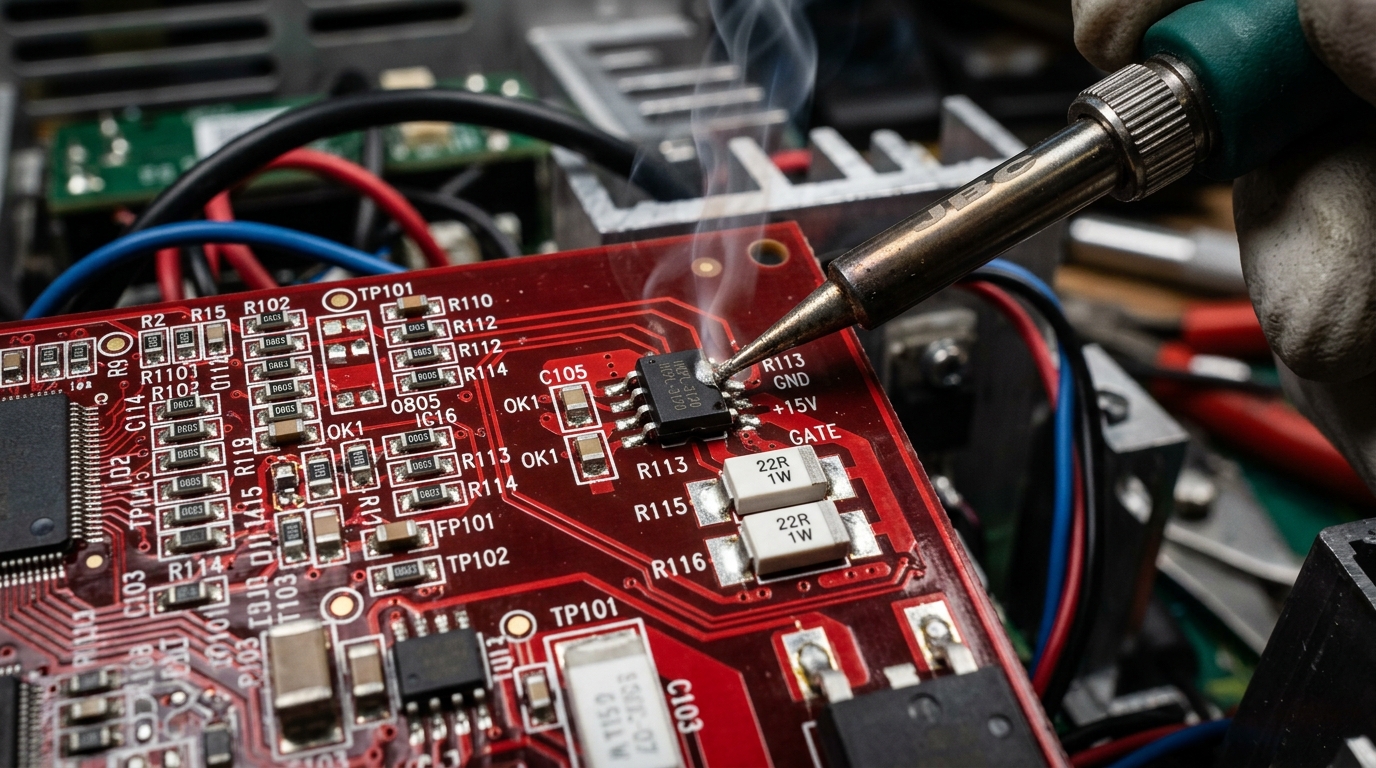
IPC-A-610 Micro-SolderingOnce the power module is disassembled inside our ESD-safe workstation, technicians extract existing drive parameters via USB MainsFree programming or direct EEPROM backup. The multi-layer power and control PCBs undergo stereo microscope inspection and prophylactic component replacement:
- SMPS Rail Rebuilding: All secondary smoothing capacitors on the
24VDCcustomer I/O rail,5VDC / 3.3VDClogic rails, and isolated gate driver power supplies are replaced with 105°C low-ESR industrial-grade capacitors, ensuring peak-to-peak voltage ripple stays below15mV. - Safe Torque Off (STO) & Gate Optocoupler Replacement: Dual-channel STO safety optocouplers (terminals
S1, S2, S+) and all six PWM gate driver optocouplers are replaced as a matched set to eliminate propagation delay skew and intermittent Safe Torque Off faults (F105 / F106).
Stage 3: Variable DC Bus Reforming & 4-Channel Oscilloscope Gate Waveform Validation
PWM Symmetry & Dead-Time CheckPrior to energizing the newly installed Frame C IPM under high voltage, the power board is powered via a current-limited variable DC bench supply. Technicians verify pre-charge relay pull-in voltage, confirm accurate DC bus voltage telemetry in Parameter b005, and capture all six upper and lower gate-to-emitter PWM drive waveforms on a 4-channel isolated digital storage oscilloscope across 5 Hz to 60 Hz command frequencies—verifying crisp rise/fall edges (<150 ns), dead-time interlocking, and firm negative turn-off clamping.
Stage 4: 480VAC Closed-Loop Dynamometer Full-Load Burn-In (17 Amps / 10 HP)
100% Rated Torque ValidationNo PowerFlex 525 leaves our Virginia bench tested only on an unloaded demo motor. The reassembled 25B-D017N104 is mounted to our 480VAC closed-loop dynamometer test stand driving a 10 HP NEMA Premium induction motor coupled to an active absorption brake. The drive is subjected to continuous full-load operation at 17.0 Amps continuous output, cyclic acceleration/deceleration torque steps, and dynamic braking load dumps while FLIR thermal imaging cameras verify uniform heatsink temperature distribution and cooling fan airflow.
Need Immediate Repair for a Faulted Allen-Bradley 25B-D017N104 Drive?
Don't wait weeks for backordered OEM replacements or risk production downtime with untested surplus drives. Ship or drop off your faulted 25B-D017N104 PowerFlex 525 at our Chantilly, Virginia bench laboratory for a 100% free component-level evaluation. We back up your existing parameters and offer 24–48 hour emergency rush turnaround.